A Digital Height Gage with cast iron base, A work in progress
I wanted a 2nd height gage to use on my surface plate, but it was not a big need.
I found a design digital height gage mentioned here, and it gave me the inspiration to build one myself. Harbor Freight had the digital calipers on sale so I picked a few up with this project in mind.
Looking around the shop for a suitable base I found an old crank out of a Briggs and Stratton 5 HP Horizontal engine. Its nice to have a good junk box of stuff you will probably never use! It would make a fine base for my Height Gage.
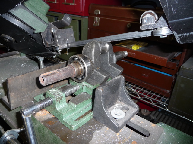
 Cutting the crank on the Band Saw. I first grabbed it in a drill press vise then clamped the drill press vise in the bandsaw.
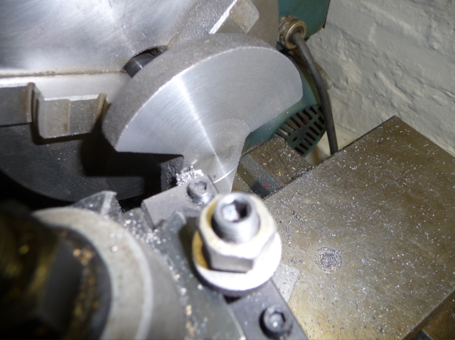
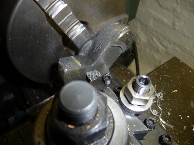 Now it was over to the lathe to turn what would be the bottom of the Height Gage flat and true. I left the flywheel side on the crank web so I could chuck it in the 3 jaw. I had a lot of problems turning down the crank. The outer skin of the cast iron was very hard. The interrupted cut as you get out to the edges proved to be more than my HSS lathe bit could take. Persistence, a few choice words, and lots of time re-sharpening the tool eventually paid off. The other thing that I found was to take very small cuts, and keep the RPM of the lathe to a minimum.
Once I was down to good metal it turned real nice. I switched to a finishing tool and faced off the base smooth.
Here I am cutting away most of the center of the base. This will keep it from wobbling on the surface plate. I left about 1/2 inch on the outer most edge of what will be the bottom of the surface gage. You can see this in the photo below.
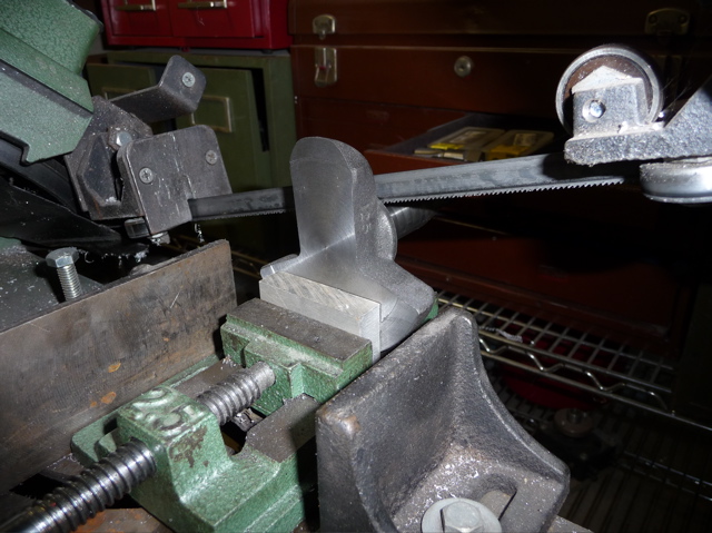
Back to the saw to cut off the part of the crank I had left so I could chuck it in the lathe. The aluminum packing in the vise is just to protect the newly machined surface.
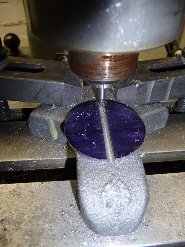
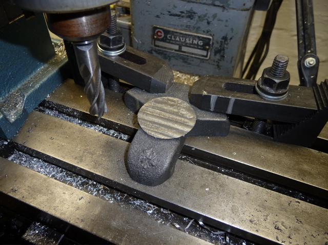 Here I bolted the finished base to the milling machine table. I used a 1/2 inch endmill to mill the top off were the digital calipers would be mounted. This surface does not have to be as smooth as the bottom. I will most likely fly cut the top surface later to make it look nice.
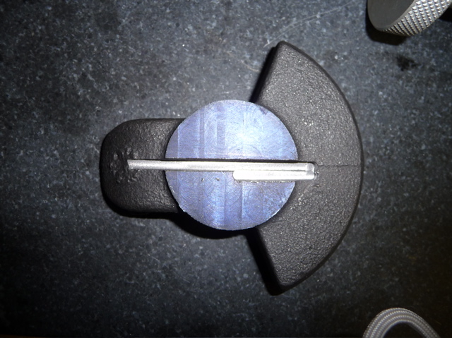 When fully closed the calipers overlap at the foot. To allow for this I milled an additional slot in the base, as can be seen in this photo.
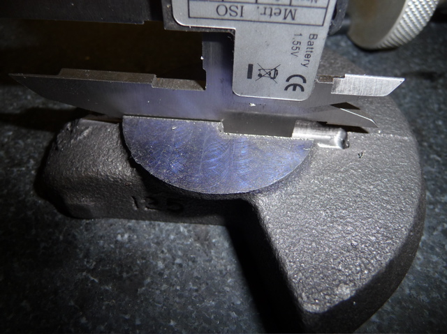 Here I am test fitting the caliper into the base.
Now I just need to secure the calipers in the base and build the scribing arm.
More to come!
