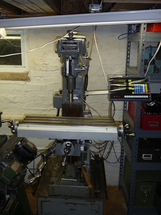
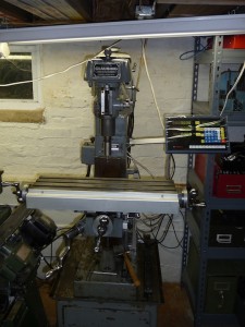
I had been wanting to add a DRO to my Clausing for a while now As the bearings in the cross feed table needed to be replaced, I thought it would be a good time to install the DRO while I had it down for repair.
After some research I decided on the mTech TDS 3i from thedrostore.com. I measured the mill and choose the standard JCXE scales This is what was ordered for the mill.
- TDS 3 / TECH-3I / MEA-3 (3 Axis LCD DRO)
- Scale Travel length -JCXE5:170mm, 6.7inch (Physical length:312mm, 12.3inch)
- Scale Travel length -JCXE5:320mm, 12.6inch (Physical length:462mm, 18.2inch)
- Scale Travel length -JCXE5:420mm, 16.5inch (Physical length:562mm, 22.1inch)
Total with FedEx international shipping was $510.00
An interesting note, 3 moths after receiving my DRO I received a bill from FedEx for $17.50 which was the customs/import fees for the package. After talking with FedEx they apparently pay these fees to clear the package and not hold it up and then bill you for them at a later date.
My order was placed on June 10th 2011. The following day I received a conformation e-mail from Scott confirming my delivery address and the scale lengths that I chose. I sent payment via PayPal and received my tracking number the following day.
My order arrived on Friday June 17th at my office. As my luck would have it I was not at the office that day. I had a co-worker who I would be seeing later that night pick up my package for me so I could look at it for the weekend. It came in two well packaged boxes one containing the display, and another containing the scales.
I assembled the DRO on the work bench and tried everything out. The scale encoders are mounted to the scales with two small plastic holders to secure them during shipping and assist in installation. I temporarily removed them, everything seemed to be in good working order. I took some measurements and started planning the install. Included with the DRO are mounting brackets of different sizes and shapes. It turns out I did not use them on my install, as I chose to mill my own mounting brackets.
The shaft to raise and lower the knee on my mill did not run true and had a slight wobble to it. It was this way when I purchased it. As it did not affect the operation, I had lived with it. Now was a good time to fix that also. The plan was to just straighten it out while I had the mill apart. That did not work out as planned. It was deformed around the bearings, and my attempts to straighten it while in the knee were not very successful. In fact, to even remove it from the machine would require me to cut it in half to keep from possibly damaging other parts. Here is a tip if you ever run into a situation like this. Make two marks on the shaft at a known distance on each side of location where you plan to make your cut. I had to guess at the shaft length on the replacement. If I had marked it first, I would know exactly the correct length the shaft should be. Saws-All’s do not make good clean cuts. Lessons learned.
The Bronze bushing that goes in the knee was also in bad shape, so it was replaced with one I turned up on the lathe. Somehow, I have misplaced the photos of all of this work, when I find them I will upload them here.
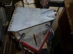
The next order of business was to drill new mounting holes in the knee to mount the DRO scales. I did this on the drill press. There were already two taped holes on the knee that I could have used, but I chose to drill 4 more towards the bottom for my installation.
I also drilled some extra holes on the opposite side of the knee while it was off the machine for the later addition of a power feed on the z axis feed.
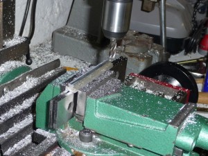
This is the only photo that I have of this operation.
The knee was mounted to the drill press, and all holes were taped 10-32. This is the power feed holes being drilled.
Note: Something you need to think about before starting something like this. How are you going to get the work done without your mill? I happen to have a large floor mounted drill press, and a Mini-Mill in the shop, but if you only have 1 mill, you will need to plan carefully so that you can mill as many of the pieces as you can before disassembling the mill to install the DRO. I was planning on selling the mini-mill but after using it so much while this mill was down, I have decided to keep it.
-
Machining the small T-Nuts
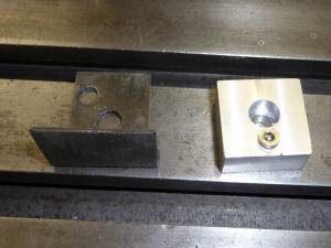
To mount the X scale on the front of the table I decided to use the existing t-slots. The only other option would be to mount the scale on the rear, but I would have lost almost an inch of movement. This was not a good option for me. The T-Slot is used mostly for mechanical stops which I figure I can live without once the DRO is installed. I made some small T-Nuts to fit the front of the table. They are taped 10-32 this allows the bolt to clear the mounting holes in the scales.
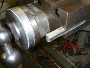
Here I am test fitting the t-nuts I made for the front table slots.
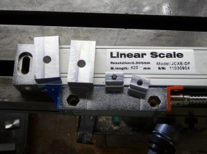
Finished t-nuts and the spacers to bring the scale out away from the table.
On the front of the table there is an oiler port built into the original table stop. I made a replacement and used an oiler port that I had on hand from littlemachineshop.com There is also a small L bracket that goes under the oiler the covers up part of the metal shield to keeps chips off the feed screw, which I reused. I did not duplicate the roll pins that are in the original. They are not needed as it is no longer used as a table stop.
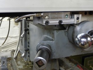
There were two small tapped holes on the front of the knee already. I fabricated a small mount for the scale encoder to fit using the existing holes. I chose to mount the encoder to the side of the table instead of the center. This allows access to the oil port, but as a result I lose about 2 inches of travel. I need to install a mechanical stop to keep from running the table too far and hitting the encoder. I plan on adding a power feed to the mill shortly and will be installing auto electrical stops so I did not install them at this time. There is enough room to move the encoder to the right about 1 inch or so. I will need to build a longer bracket and will probably do at a later date.
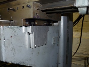
While I had the table off, I drilled two holes on the bottom of the Y slide. These 10-32 tapped holes just clear the gib adjustment screws on the slide. I made an aluminum bracket to mount to the bottom of the slide that just clears the knee. Here you can see the small raised surface on the knee that had two holes already tapped. But using it for the Z axis would interfere with the Y access scales. That is why I choose to drill the four holes for the Z axis lower on the knee.
I drilled the two holes in the knee to mount the scale. after dry fitting the scale on the lower side. Small spacers were machined to hold the scales out the correct distance to align the encoder. A short cover will go over this to keep the gib locking lever from hitting the scale, as well as to help keep chips clear.
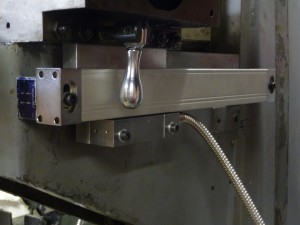
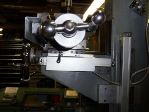
Here you can see the cover added. It does not cover the full length of the scale, as it is attached to the slide and moves with the table. It does keep the gib lever off the scale, and covers the encoder. The open end of the scale is pointed down so there is little possibility of chips getting in the scale.
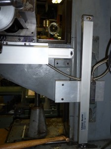
This photo also shows the mounted Z scale. A 1 inch thick piece of aluminum bolted to the knee. A 3/8 inch thick plate is bolted onto that to reach back along the column. This was needed as the column is much wider than the knee. The metal used is real overkill for what is needed, but I had it on hand in the scrap pile. The Z scale encoder is mounted to the 3/8 inch plate. I had a little clearance problem with the Clausing name plate so I chose to remove it.
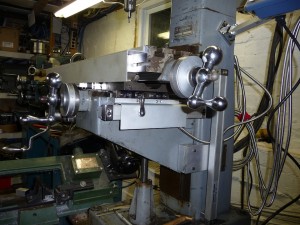
Here you can see all the scales mounted on the mill.
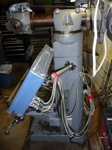
I mounted the bracket to the mill at an angle so that it was a little higher and at a comfortable angle when standing in front of the mill. I need to do something with the excess length of the cables. I have not decided yet if I can just going to coil them up or shorten them. If I shorten them, I will have to remove the connectors cut the cables and solder replacements on.
Here is another view that shows the cover installed over the front scale. I had to add a small 1/4 x 1/2 inch length of aluminum as a spacer to clear the scale. The cover is attached to the table and is an exact fit for the table length. Sometime things just work out. I need to make a replacement table lock for the front. The Clausing one is not ideal. I need to build one that has a ratcheting handle as there is very little room left.
Here it is from the front. All tests prove that it is very stable and repeatable. The DRO matches with the dials over the length of the table.
The manual is just horrible! The English translation is some of the worst I have seen.
One thing I noticed right away is that the manually entering values into any of the display’s settings, forces you to enter decimal numbers as 0.001 if you do not prefix it with the 0 before hitting the “.” it will interpret the number as 1 inch. It also has an issue with using the built-in calculator. When you store the result to one of the axsis it wants to use the metric value, even if the DRO is in inch mode.
The 4th decimal place on the display when in inch mode is also very distracting. I covered it with the piece of electrical tape. – Later I found a setting in the menu that I can truncate the decimal places in the settings.
After using the DRO my biggest complaint is that the zero buttons are not aligned with the corresponding display. This has taken some time to get used to. But all in all, I would not want to go back to using my mill without the DRO installed. Well worth the effort and price.
