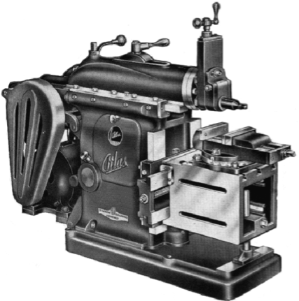
This is a collection of information that I have gathered on the Atlas 7 inch metal shaper, Some of the information I have authored, and some that I have not.
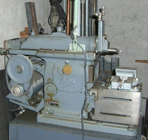
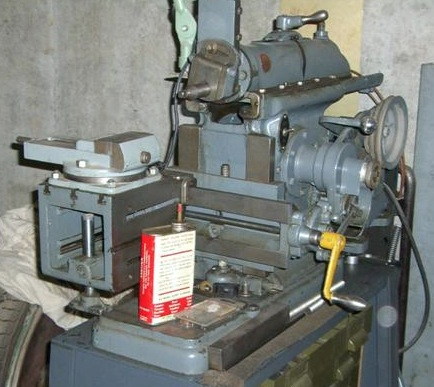
In June of 2009 I purchased an Atlas Shaper, It was complete except for the extension to the factory crank handle. I also include a factory vise. On my model the belt guards, were offered as an option. Which I did not receive with the shaper. The condition of the shaper was very good, upon inspection there is little to no wear on any of the moving surfaces. Some of the adjustment screws and fasteners have been painted over, I believe that at some point in its life it was repainted. Under the gray paint appears to be a green paint, I do not know if this is a primer or its original color.
By all accounts it is a model 7B, but the name tag is marked 7AB, carrying the serial number of 2374. This has been somewhat of a mystery as no-one had ever seen or heard of a model 7AB. But I have uncovered evidence that this model was offered from Atlas. The Model 7AB is simply a Model 7B that shipped without the Safety/Belt guards. I found this ad from Atlas clearly listing the 7AB Shaper. There was no year of publication
I found my shaper on Craig’s List, and was only about 5 miles from my location. These two photos are of the shaper as I purchased it. Unfortunately the seller would not sell me the stand it was sitting on, which was custom built by his father.
Documentation
- Atlas Parts List and Catalog for the 7B Shaper
- Atlas Shaper Brochure
- Atlas Catalog from 1937 1945 and 1952
- Atlas Price List from 1944 and 1956
- Atlas Machine Cabinets Brochure 1943
- Craftsman 1959 Catalog Page Listing Shaper
- Atlas 7B Clapper Detail
- Know your Shaper – Details on the Atlas Shaper by Sam Brown
- Contour Cutting with the Atlas Shaper by Sam Brown
History
Atlas started manufacturing the 7 inch shaper in 1937 which sold for $198.00. It was discontinued in the year of 1961. This shaper was also sold by Craftsman/Sears under the part number 99-LR-M1600F and in the UK under the Acorn name.
Page from the 1959 Craftsman tool catalog showing the shaper and accessories.
Options
Belt / Safty Gaurds
The shaper was offered early on with the Belt Guards as an option. Later catalogs only show the shaper available with the belt guards included. This ad clearly shows the model B and Model AB (That I Have) did not include the guards. None of the price lists or catalogs show the guards afford as an stock option.
Vise
The vise was included with the shaper. The atlas price lists and catalogs do not show the vise offered for sale as a separate item.
Motor
The shaper was sold with out a motor. Many motors were offered from 110 Volt to a 440 volt three phase.
Motor specifications
- 1/2 HP
- 1725 RPM
- 1/2 inch single ended shaft.
Stands
Floor Stand Metal
- Part Number S7-442C
- Cast Iron Lets
- 1 5/8″ Hard wood top.
- 138 Lbs
Floor Cabinet Wood
- Part Number M1-750
- Covered Compartment for tools and accessories
- Hardwood Construction
- 140 Lbs
Cabinet Sheet Metal
- In 1950 Atlas offered a sheet metal cabinet for the shaper
- Sears offered this same stand in their catalog
- Part number #9050
Tool Holders
Two Tool holders were offered as well as replacement pre-ground HSS bits.
Standard Tool Holder
- Part Number S7-139
- Rigid holder for working at all angles
- Uses 1/4″ high speed cutters.
Extension Tool Holder
- Part Number S7-315
- Provides Extra clearance for intern work
- Drop Forged
- Broached hole for 3/16″ cutter bits.
Index Centers
- Part number S7-400
- Distance between Centers 8″
- Maximum Swing 5 1/2″
- Base Dimensions 14 1/4″ x 6″
- Furnished with two index plates (30,36 Holes – 28,48 Holes) and Clamp Dog
Rotary Index Table
- Part Number S7-420
- Precision Ground
- 3 T Slots
- Holes in sides every 30 Deg.
- Graduated 0 – 90 Deg.
- Table Diameter 5 1/2″
- Height of Table 1 7/8″
Atlas Angle Plate
- Part Number S7-430
- A solid well-graced iron casting.
- Precision ground on outer faces
- 4 Holes for Bolting to table
- Measures 2 1/2 x 4 x 7/16
Table Extension
- Part Number S7-435
Grinding Attachment
In 1940 Atlas offered a grinder for the shaper. It mounted in place of the clapper box. It was not in their catalog for very long as it had disapeard by the time their 1941 catalog came out. It appeared on Page 54 of the 1940 catalog.
- Part Number S7-450
- Equips the shaper for fine surface finishing
- Mounted in place of the clapper head
- Lubricated-and-sealed-for-life ball bearing spindle
- Uses 2-1/2 OD wheels: #475–for Steel; #476–for CI
- Dumore motor w/2-step pulleys: 6800 & 10400 RPM
- Dumore motor is universal: 105-125 AC x~xx 25-60 Hz; 105-125 DC
- Motor w/hinged base for belt adjustment
- Supplied with safety guards/shields for wheel and belt
- Diamond wheel dresser provided
- Weight: 22 lbs (10 Kg)
- 1940 price: $42.50
Parts
Clausing who purchased Atlas had a few parts and copies of the manual in stock for the shaper.
Replacement Castings for some of the parts might still be avalable from Harprit Singh
Reproduction Belt Guards
At the time I purchased my shaper reproduction aluminum Belt guard castings were available from Dan at dan@hillsgun.com The small guard was $85.00 while the large guard was $140.00. Check with Dan for current pricing and availability.
Other Parts
eBay usually has a listing of shaper parts from time to time.
Repair Information
Belts & Pulley Info
-
- 1/2 inch standard V belts
- Left Side 29 Inchs (4L290)
- Right Side 32 Inchs (4L320)
- Countershaft driver is a 4 step pulley….3.0″, 4.0″, 5.0″, and 6.0″
- Matching step pulley on the bull gear shaft.
Replacement Gear S7-81
-
- 2.5″ diameter pitch circle
- 40 teeth
- 16 pitch
Clapper Box Taper Pin Fitting
By John Lawson
I have fitted up a number of loose clappers successfully and I will set forth my method for those who may be interested. The taper pin is designed to be a tight (non-moving) fit on the mount sides and a loose (but shake-free) fit on the clapper. The nut on the end of the taper pin is 5/16″-18. There is an oil hole on top of the clapper that is usually overlooked. Every time you use your shaper you should put a few drops of oil in the oil hole, swing the clapper out and put a few drops of oil on both sides. It should swing free
without any lift, shake or looseness. When the taper hole through the clapper wears oversize, or when the taper pin wears where it passes through the clapper, the obvious quick fix is to put a wrench on the nut and try to draw it in, making the clapper tighter. NOT! The pin is already tight on both sides of the mount. Reefing on the wrench handle usually breaks the nut off the end of the taper pin. If enough mayhem is indulged in, you may break part of the casting.
The replacement taper pins will not tighten up a worn taper hole through the clapper. Besides a replacement taper pin, you will need a #8 taper pin reamer. These are reasonable from J&G. Actually, you may as well order a pair of Morse Taper reamers for your lathe’s headstock and tailstock ram and spindle at the same time, if the sockets need a touchup. My reamers are imports from Spain, and they work just fine.
After removing the old taper pin, place the clapper back in alignment and carefully ream through the support and clapper. Take out minimal metal; you just want to clean up a worn taper hole through the clapper with the proper enlargement of the supports. Remove the reamer and clapper. Insert the reamer in the clapper and ream just a very slight amount; only enough for the clapper to move freely without shake when mounted. Tap the head of the taper pin lightly with a soft hammer to srt. Check clapper movement. IT MUST MOVE FREELY WITHOUT SHAKE. Tighten the nut in place. Do not reef on the nut; the taps with a hammer set the pin in place immovably. The nut is to keep the pin from backing out. Now, you have a clapper that will produce perfect cuts. If you can’t obtain a replacement taper pin, buy a few #8 taper pins from your local screw and fastener supply. Bore a through hole in a short piece of 3/4″ diameter drill rod. Insert the taper pin and tap in place with a soft hammer. Mount small end out in your lathe chuck. Turn the taper parallel with a carbide bit. Thread 5/16″-18 and cut off the excess. (Note that these taper pins come in various sizes; get the proper size for your needs.) You may want to change the position of the threads slightly.
Lubrication
By Unknown
The Atlas shaper was designed in the days when chassis lube grease was used exclusively. The modern greases…and the white type is a teflon base that is very good and very long lasting…are better applied with a small grease gun instead of the rather crude screw on cap. Simply replace the grease application device with a zerk fitting and you can pump grease all the way into the proper position without excessive messing around. You can save the screw on fitting with your spare parts in case you sell your shaper to a purist at some future date.
RAM Stroke Length adjustment
By Dick Farris
To adjust the stroke length, place the crank on the square-end shaft
INSIDE the large hand nut which revolves with the bull gear. Hold the
hand nut with the left hand and turn the crank a half-turn to the right
with the right hand. This loosens the crank shaft.
The RAM should have been revolved by hand to the extreme end of the
return stroke. Turn the crank and watch the pointer and scale. The
pointer shows the length of stroke directly in inches. Get to where you
want to be and hold the crank steady and turn the hand nut to the right
until it stops. Lock the hand nut by holding the hand nut steady and
turning the crank to the left. Never strike the hand nut with anything.
Shim Stock
Found under the Gibs a good Peel away replacement is avalable from McMaster-Carr Part number is 9521K33 It is .010″ in Overall Thickness make up of .002 Thick Brass Layers.
Ram Removal
By Tom Peterson
Note that the S7-118 Gear has a pin through it affixing it to the S7-37 screw. There is a hole on the top of the ram through which you can wield a pin punch to drive out the pin. After removing the jam nuts on the aft end of the S7-37 screw you can slide the screw forward. Other parts will have to be removed (ram plates, wiper shields, etc.)
before the ram itself can be removed.
To remove the ram position adjustment gears, bevel gear (s7-118) and bevel gear with shaft (s7-103), located in the ram, you must first knock-out the pin which retains the gear on the horizontal screw shaft. Directly behind the vertical shaft on the ram is a hole. The hole is used to knock-out and insert the pin that holds the gear on the screw shaft (s7-37). My pin was tapered and could only be knocked out in one direction. Once the pin is out, remove the jam nuts on the back end of the screw shaft (s7-37). Then loosen the ram clamp and move the ram backward allowing room for the gear, bushing and washer to slide off the end of the screw shaft. Once these parts are out, loosen the collar (BD1-24) and drop the vertical shaft and gear down out of the ram. Also, I think I removed my drip pan off the back of the shaper to make it easier to work on.
My gears were broken when I got my shaper and I worked for a year manually adjusting the ram position. With all the ram adjustment parts removed, you can position the ram by hand. Then, I decided to fix it.
I got two matched bevel gears from MSC that were close in size and machined them to fit. Basically, I had to remove metal from the back of the gears and drill/bore out center of one of the gears. Also, drill the hole for the retaining pin. Pretty basic lathe/drill press work.
Item# 36682789 – 12 PITCH 18 TEETH MITER GEARS 2 x $16.72 totaling $33.44
Shaper Resources elsewhere:
More Shaper Information.
- Old Iron (Atlas shaper, restored) by Rudy Kauhoupt
- Home Shop Machinist Unknown issue date.
- Reprinted in “The Shop Wisdom of Rudy Kohoupt, Volume Two.”
- Available from Village Press
- “The Shaping Machine by Ian Bradley, published by MAP in England.
- One of the best books covering the shaper.
- Now out of print
- Bradley shows how to build a power downfeed device and many other innovations not available elsewhere.
- The New England Model Engineering Society has a copy on their web site.
Videos
- Bay Com offers two videos by Rudy Kohoupt for sale.
- Smart Flix Offers them for rental for only $10.00.
-
- Kay Fisher’s Metal Shaper Columns
- Atlas Shaper Yahoo Group
- James Riser Altas Shaper Pages
- Tony Griffiths Wonderful Atlas Shaper Pages
- Articles from Popular Mechanics and Popular Science
- Metal Shaper FAQ
- NEME’s Shaper Book Page
- Don’s page has info on cutting gears and splines as well as plans for a toolholder.
- Drawings for Shaper Tool Holder
- Atlas 7b Clapper Box Detail
- High quality scans of manual
- Lots of archived info on shapers at JanelleStudio


