QRP Broadcast Interference High Pass Filter.
I suffer from AM Broadcast interference at my QTH. My larger HF rigs do a good job of filtering this out, but many of my QRP rigs do not.
I recently built a TrUDX as well as purchased a Xiegu X6100. Both have wide open front ends and suffer from overload from the AM broadcast signals on most bands.
I wanted something for a permanent installation at my home station, as well as a portable solution for remote operations. A little bit of Google Foo turn up an article by VK3IL on a filter he designed.
https://vk3il.net/projects/broadcast-band-filter/
As the portable filter will work at home as well as in the field I decided to tackle that one first.
I first needed to scale it down into the 10 or 15 watt range. I chose to design the filter around the T50-6 toroids as they will handle about 20-25 watts into a resonant antenna as well would fit into a 25mm or 1 inch case which is the perfect size for my needs.
A perfect size case was found on Amazon.
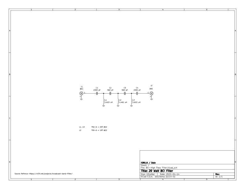
Bellow is the winding info for the T50-2 toroids. I also chose to use surface mount capacitors from DigiKey to save space.
T1, T3 - 20 Turns of #22 enameled wire on T50-6
T2, - 19 Turns of #22 enameled wire on T50-6
C1,C4 - 1500 pF 630V C0G 1206 DigiKey# CGA5H4C0G2J152J115AA
C2,C3 - 560 pF 630V C0G 1206 DigiKey# C3216C0G2J561K085AA
The filter works very well. It blocks everything bellow about 3Mhz, and has very little loss across the HF bands.
160 Meters is not usable with the filter as it will block it. But I do not operate 160 Meters QRP anyway. I will have to solve that one for my permanent QTH filter.
The filter also is usable on 6 Meters but it does introduce some loss once it gets to that band. If I am operating 6 meters QRP I can simply remove the filter.
I recently built a TrUDX as well as purchased a Xiegu X6100. Both have wide open front ends and suffer from overload from the AM broadcast signals on most bands.
I wanted something for a permanent installation at my home station, as well as a portable solution for remote operations. A little bit of Google Foo turn up an article by VK3IL on a filter he designed.
https://vk3il.net/projects/broadcast-band-filter/
As the portable filter will work at home as well as in the field I decided to tackle that one first.
I first needed to scale it down into the 10 or 15 watt range. I chose to design the filter around the T50-6 toroids as they will handle about 20-25 watts into a resonant antenna as well would fit into a 25mm or 1 inch case which is the perfect size for my needs.
A perfect size case was found on Amazon.
Bellow is the winding info for the T50-2 toroids. I also chose to use surface mount capacitors from DigiKey to save space.
T1, T3 - 20 Turns of #22 enameled wire on T50-6
T2, - 19 Turns of #22 enameled wire on T50-6
C1,C4 - 1500 pF 630V C0G 1206 DigiKey# CGA5H4C0G2J152J115AA
C2,C3 - 560 pF 630V C0G 1206 DigiKey# C3216C0G2J561K085AA
The filter works very well. It blocks everything bellow about 3Mhz, and has very little loss across the HF bands.
160 Meters is not usable with the filter as it will block it. But I do not operate 160 Meters QRP anyway. I will have to solve that one for my permanent QTH filter.
The filter also is usable on 6 Meters but it does introduce some loss once it gets to that band. If I am operating 6 meters QRP I can simply remove the filter.
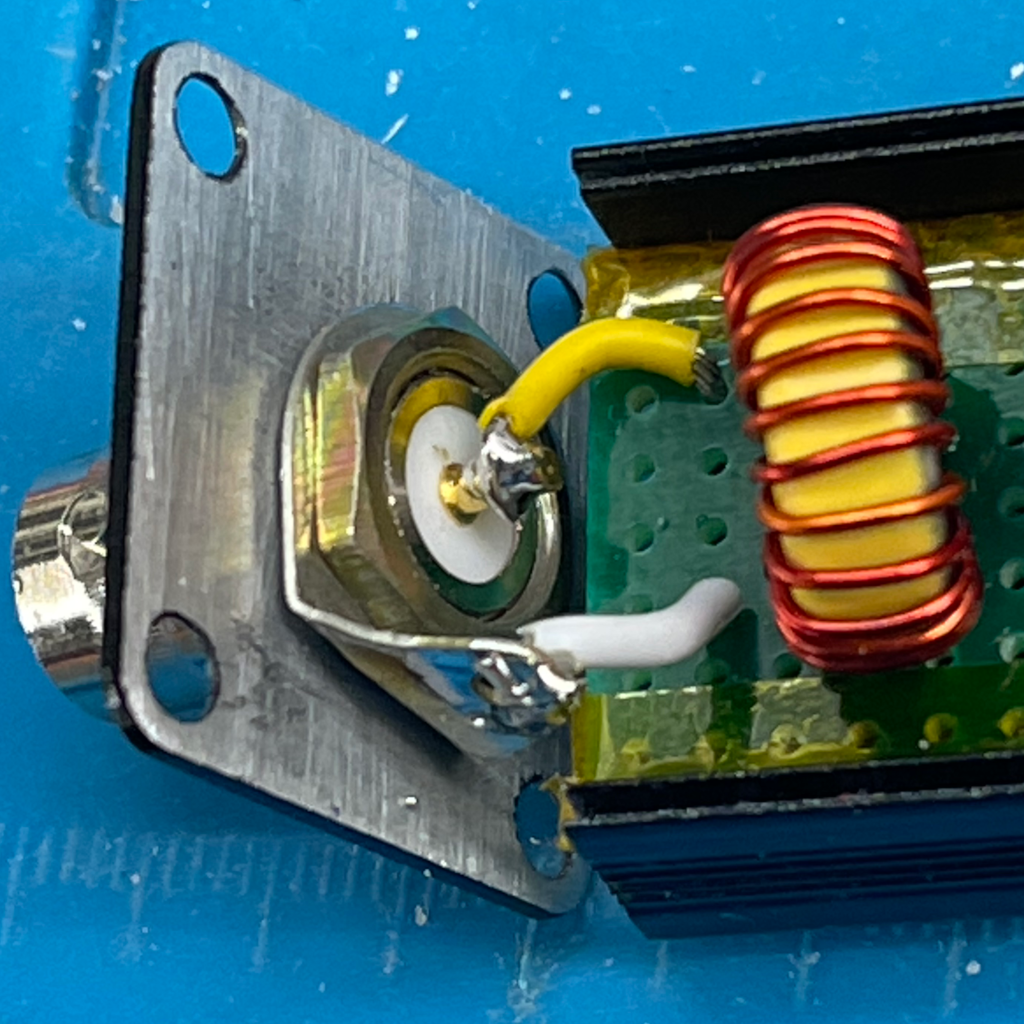
The T50-6 Toroids are mounted at right angles to keep them from interacting with each other. As the case I chose was rather small, I had to use short mounting BNC connectors which I had on hand. These are not common and I would recommend a slightly longer case if you plan on using BNC connectors. The short wires are just long enough to allow the case ends with the BNC's solder in place to be moved out up to clear the case half when the board is slid into its mounting slot.
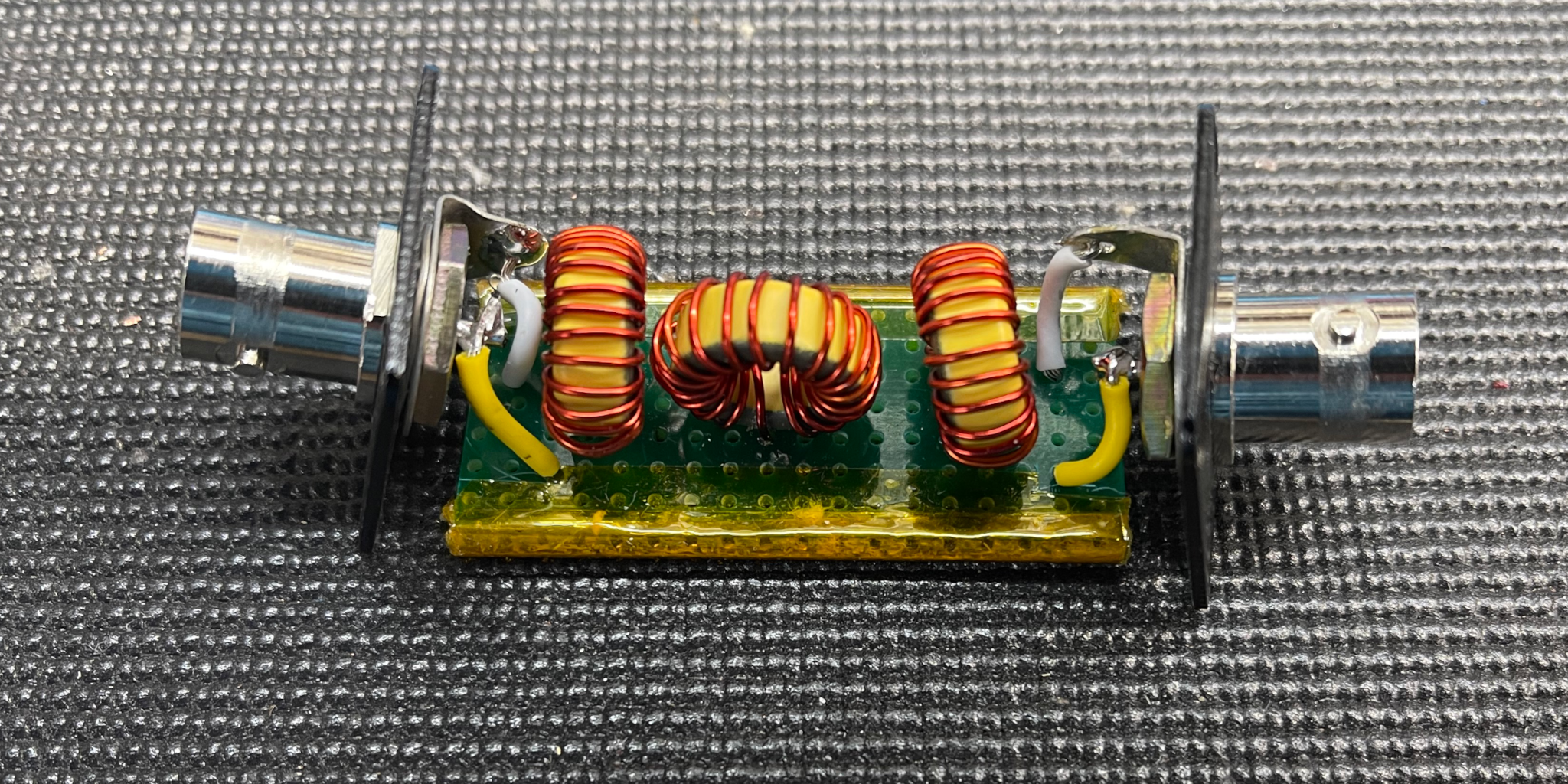
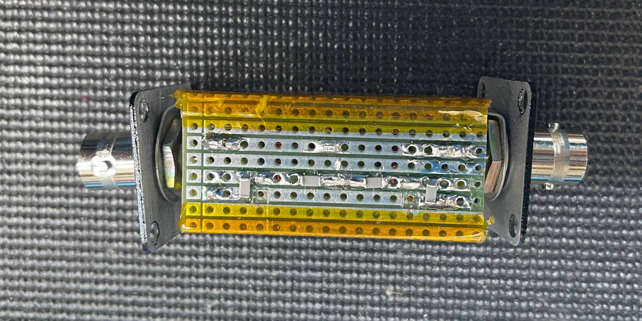
I used Stripe Board as it works well with the mix of through hole and surface mount components. The Kapton tape on the edge of the boards is there only to allow a snug fit of the board in to the case. The slots in the case are a bit thicker than the circuit board.
The case was purchased from Amazon, they are also available on Ebay. It is a 25x25x40 mm extruded aluminum case. It is nicely powder coated on every surface. I sanded the coating off the inside of both ends to allow the BNC connector to make good electrical contact. I also sanded the coating away from the ends of each case section so they could make a good ground connection to the ends. This ensures that the case is fully grounded and shielded. Originally I prototyped this build dead bug style with out a case. With out the shielding of the case I still got a bit of interference. I would highly recommend using a fully shielded metal box for this project.
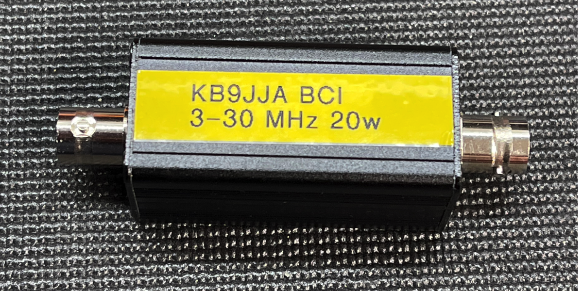
The finished BCI Filter. It is actually usable into the 6 meter band but has a higher loss than on the HF bands.
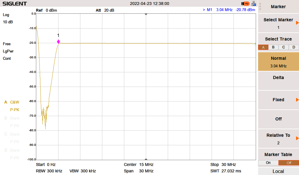
SA sweet 0-30 Mhz. Filter is 50db down in the range where we want it, and pretty flat though 30 Mhz.
The SA is sweeping with a -20dBm output on all photos
The SA is sweeping with a -20dBm output on all photos
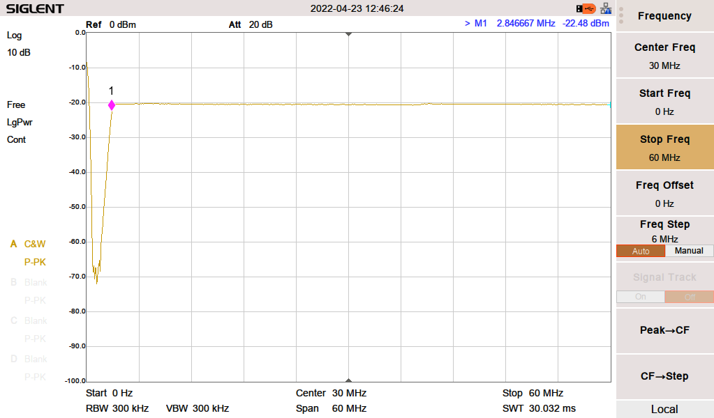
It's still perfectly usable out to 60 MHz, should not be a problem on 6 meters at all.
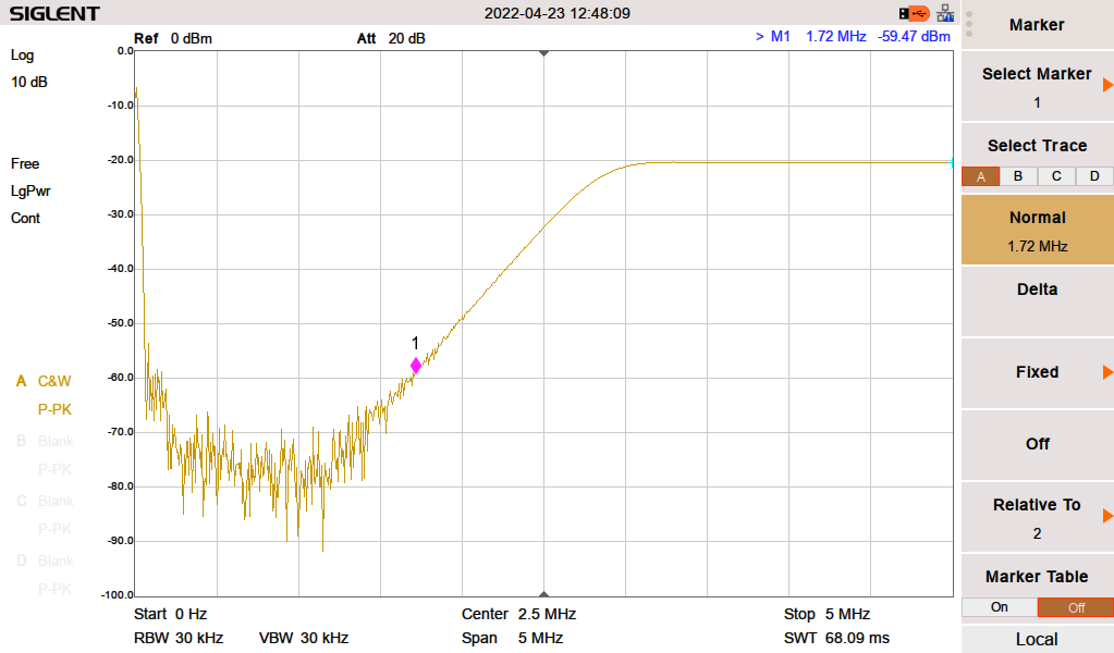
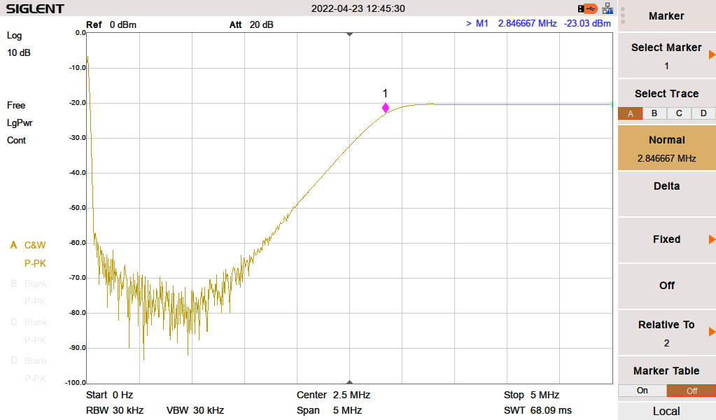
0-5 Mhz sweep showing 3 dB down point at 2.84 MHz This makes this filter not suitable for 160 Meters but that was expected.
0-5 Mhz sweep with a marker at the upper end of the AM broadcast band. 1.72 Mhz is at -59 dBm with the SA generating the signal at -20 dBm