Building a 0 - 3 GHz
Spectrum Analyser
Filter Plus Group Buy (Feb
2011)

Zip file with all the
details.
A group buy was put
together by Jim W1JGH in Feb of 2011 for a bunch of Filter
Circuit boards, plus a few other boards for use with the SMA.
The group buy is now over, and the boards are no longer being
offered.
This page is a collection of information that I gathered for my
use from multiple sources. Most notably documentation that Jim
Provided, Scotty’s and Sam’s web sites, as well as postings on
the list reflector. I thought that some of you might also be
interested in the info so I decided to make it a web page
instead of a word document. I make no guarantee to the
correctness of the info presented here. Use at your own risk,
and remember that some of these boards that were offered in
this buy were considered experimental.
73 de KB9JJA/Dale

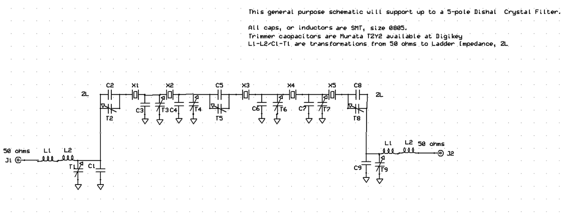
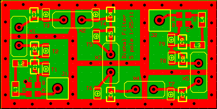
5 Pole Dishal Filter Board
All filters have provisions to utilize
surface mounts trimmer capacitors. The series TZY2 trimmers
from Murata (available at Digikey) has prices comparable to the
good quality ceramics., but the boards have pads that also
allow for the larger 1/4 inch sizes. The ceramic filter pcb is
a variation of the one available in October's group buy, it is
slightly larger and also includes pads for trimmers. This board
is well suited for wider bandwidths.

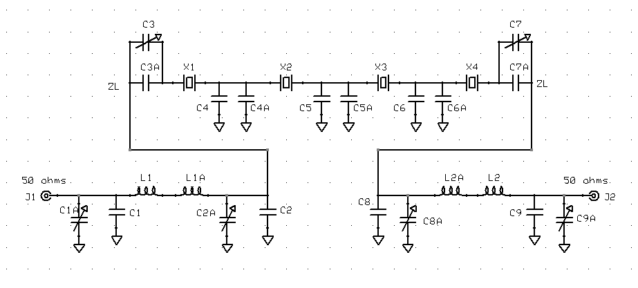
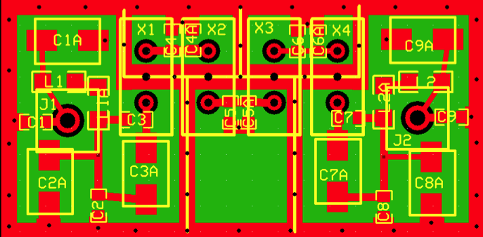
4 Pole Filter
Board

Ceramic
Filters

Hi/Lo Pass
Filters

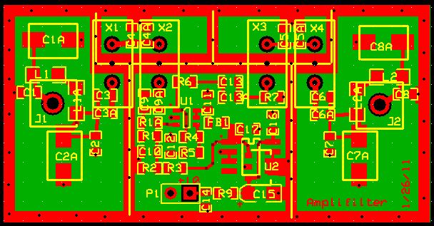
Amplifilters
The amplifilter is Sam's new addition to the arsenal. It will
house 4 crystals with a buffer in the middle. A very intriguing
experimental design.
The “Amplifilter” (I'm using Scotty's term, though the gain is
not enough to replace the IF amp) has two crystals, then a
buffer amp, then two more crystals. Hopefully it will make a
very narrow RBW filter (400-800 Hz?) that will be fairly easy
to tune. Sam W.
The amplifilter (using Scotty's term ) is Sam's
new addition to the arsenal and is a very intriguing
experimental design.. Though the gain is not enough to replace
the IF amp, it has two crystals, then a buffer amp, then two
more crystals. Hopefully it will make a very narrow RBW filter
(400-800 Hz?) that will be fairly easy to tune.
Other than resistors/capacitors, it uses
1 OPA842 op amp, SOT-23 package
1 BLM21AG102 ferrite bead
1 L4931CD80 8v LDO regulator
2 Pulse PE-0805CM681JTT 680 nH inductor
The inductors are for 10.7 MHz; for 10.1 MHz use the 750 nH
equivalent. All these parts are available at Digi-Key, except
you can get the op amp at Mouser. I was intending to find one
that Digi-Key carries, but haven't done so. The key thing is
that it be available in SOT-23 and can operate at 8V with
reasonably flat gain to 11 MHz with gain of 4. This probably
takes gain- bandwidth product of at least 200 or 300 MHz.
Correction. Mouser is now out of OPA842. OPA695 would be a good
substitute. Mouser has them; Digi-Key does not. OPA356, which
Digi-Key has, would likely work, and with that one you could
use the normal ua7805L regulator, which the PCB will also
accommodate. (In fact, with the OPA356, you have to use the 5V
regulator; 8V would blow it.).
It can use 4 of the trimmers that Jim mentioned, but I am
hoping the tuning will be simple enough that trimmers aren't
required. If adjustment is required, I'm hoping it can be done
by one-time adding or removal of a parallel cap.

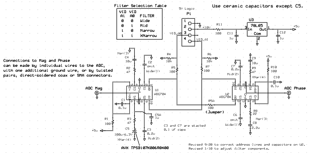
Updated Video Filter Switch
Board
(Zip file from Sam W’s site)
There is
an updated PCB for the video filter switch incorporating the
latest refinements from Sam W.
The video filter board is the same
as the one I am using now, with fixes to a couple of traces and
pads. Sam W.


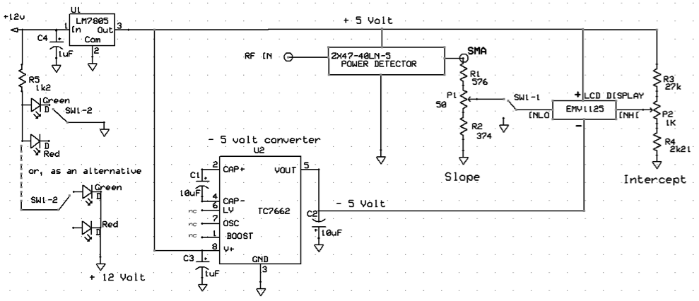
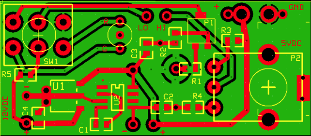
Updated W1JGH Power Meter
The power meter auxiliary board is designed
for the MiniCircuits ZX47 series power sensors. It simplifies
wiring by incorporating the calibrating pot, led and switch in
the board itself. Dan Ellis (dhellis@dslextreme.com) has got a
discount price from Mini Circuits for the sensor and he is
offering to assemble complete kits. Just get your board to him.

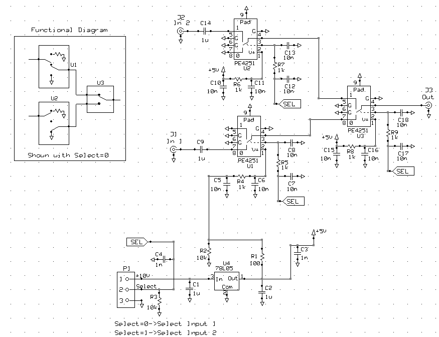
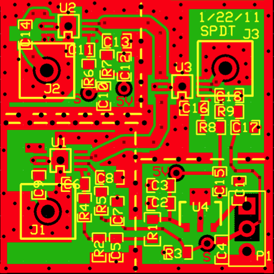
High Isolation
SPDT
The SPDT is Sam W design for a generic PE4251 filter that may
be used as a band or a transmission/ reflection switch. It has
very good isolation up to 1GHz (90 dB). The SPDT is a compact
high-isolation solid-state switch. Sam has not built this exact
one, but a similar switch performed very well. It uses 3 very
cheap PE4251s.

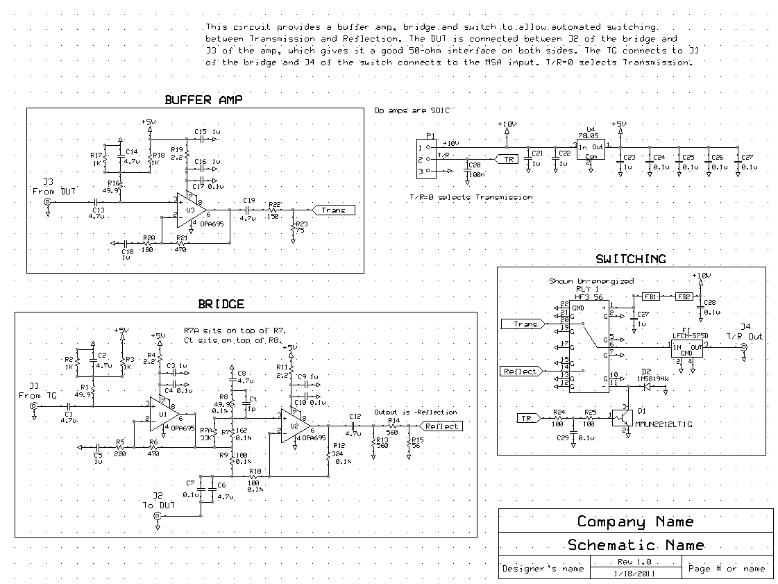
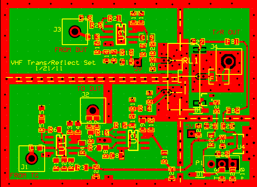
VHF Transmission/Reflection
Switch
The VHF transmission/ reflection bridge is Sam W implementation
of an S-parameter test set that should be good through 300 MHz
or so, and should be superb to 100 or 150 MHz. The set combines
a bridge and buffer amp with a transmission/reflection switch.
It's not really a full-blown S-parameter test set because it
cannot reverse the DUT. It should be accurate without the use
of 6-term or 12-term calibration, and any mechanism to reverse
the DUT screws that up. To use it, the DUT is connected between
the DUT port of the bridge and the input of the buffer amp.
This lets the DUT see solid 50 ohms on each end regardless of
the relay setting. The relay selects the bridge output for
reflection and the buffer amp output for transmission. "VHF" is
intended to convey that it does not cover the full range to 1
GHz, though it does also cover far below VHF, to 250 kHz or so,
depending how big you make the capacitors. It could also do a
nice job of displaying return loss from 250 kHz to 100 MHz with
just a spectrum analyzer with TG. We will publish the
schematics in a couple of days.
Sam wrote:
I have been fascinated by op-amp based bridges, in part because
they can perform nearly perfectly below some frequency
(somewhere in the 10-50 MHz range) and can perform very well
above that. One thing this lets you do is display return loss
graphs using just a spectrum analyzer + tracking generator. In
fact, you don't even need a tracking generator, if you have a
noise generator or plain-old swept-frequency-generator. Or,
with the MSA/VNA, scans can be made with reference calibration,
much simpler than OSL.
In some cases, it would be handy for the bridge to have a
reference impedance different from 50 ohms. 75 ohms is an
obvious possibility, but there are also situations where a much
higher impedance would be appropriate. For example, you could
get more accurate measurements of MCF filters by using higher
impedances. Especially below 30 MHz, many circuits might have
impedances much higher than 50 ohms. Likewise, there may be
circumstances where it would be nice to have a very low
impedance bridge.
I have designed a bridge whose reference impedance can be
changed simply. Different high impedances could be selected by
changing a single resistor. This single resistor approach will
work for 50 ohms and higher. Lower impedances require changing
a couple of resistors. The idea of changing resistors probably
only works if you do so only occasionally, or if you create
some simple switching method or allow plug-in resistors. The
latter approach would work, but the goal of "perfect
performance" probably limits the frequency range to <10 MHz
or so.
Sam W.
The "VHF Transmission/Reflection Set" combines a bridge and
buffer amp with a transmission/reflection switch. "VHF" is
intended to convey that it does not cover the full range to 1
GHz, though it does also cover far below VHF, to 250 kHz or so,
depending how big you make the capacitors. It could also do a
nice job of displaying return loss from 250 kHz to 100 MHz with
just a spectrum analyzer with TG. Sam W.

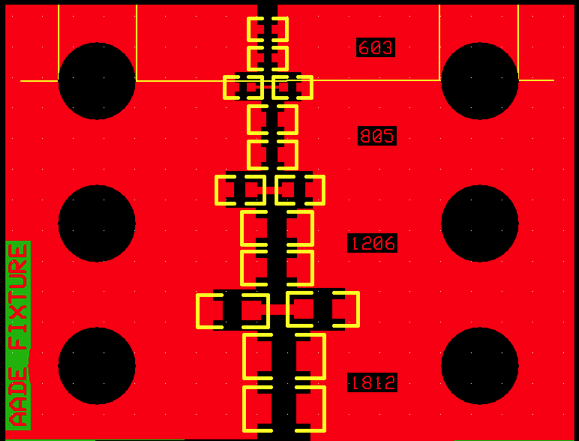
AADE Accessory Board To
Measure SMDs
The AADE accessory board l fits in the terminals of the AADE
L/C meter. It may be left permanently in place without
interfering with normal operation. By simply placing the SMD
device in the proper position and holding it in place with a
transparent plastic strip (held down by scotch tape) will let
you determine their values. It will allow for parallel and
series combinations of components.

Diplexer
PCB
Diplexer on Mixer 1 output to
simplify switching between 1G and 2G modes. 1G is the normal
0-1 GHz mode. 2G mode is 1-2 GHz. 3G mode is 2-3 GHz and
operates with the same hardware setup as 1G mode.
(See Sams Site)

Zero
response zapper PWB_RFA-1 by Scotty/SamW
(See Scotty’s Site for more
info)
-----
Hi All,
I have completed the Web Page for the Buffer Amplifier:
http://www.scottyspectrumanalyzer.com/slim_rfa_1.html
It can be used as the Buffer/Isolator between PLO 2 and Mixer
3. It is
designed to have 0 dB gain, with about -38 dB of reverse
isolation.
Scotty
-----
Scotty
pointed out that the "zero response" that actually extends up
to 1 MHz or so in VNA modes, can be significantly reduced by
adding a buffer amplifier in the path from PLO2 to Mixer 3.
This prevents LO3 from leaking back into PLO2. Essentially,
this requires 15 dB of attenuation, followed by 18 dB of gain
from an ERA-33 or similar MMIC, followed by 3 dB attenuation on
the output. I made up the attached layout for such an amp,
which is about 1.2" x 0.9" and is designed to be placed
"in-line", with its connectors sticking out each end. That way
it can be placed in the cabling from PLO2 to Mixer 3. I haven't
done the schematic yet, but it is similar to the MMIC amp on
the Signal Router board--but that one was a little more complex
because it was also designed to provide power for other boards.
This one can be built as normal MMIC-plus-inductor (the
inductor actually fits on the R6 pad), or it can be an
inductorless buffer amp such as the one I use on my TG output.
-------
Hi Jim and
All, I would point out that the SLIM-IFA-33 is a specialized
amplifier, but it is constructed on a general purpose printed
wiring board called "PWB_RFA". You can build the 1024 MHz
buffer amplifier on this pwb by replacing L1(L2) with a 68 nH
or similar choke. Replace the filter circuit (C26,L27,C28) with
an appropriate resistive pi type attenuator. You can add the 15
dB input attenuator (resistive pi type) to the pads at X21, X22
(R22), and X24. Also, this is a dual amplifier board and
you need not populate the U2 side. I will update the web
page for this pwb. Scotty
------
Yes,
the PWB_RFA will work well for the PLO2
buffer amp. The board that is included on Jim's PCB has only
one amp stage and is slightly down-sized to 0.9"x1.2". It is
designed to have connectors sticking out opposite ends,
which might be more convenient if you don't want to actually
mount it in the grid, but want to have it "float" in the
cabling. But if someone has an extra PWB_RFA, there is no
strong reason not to use it.
The other thing this board will accommodate is a
1206 resistor in place of the inductor. This lets you build a
broadband amp that extends to fairly low frequencies, so long
as you accept lower gain, which is perfect for something such
as a TG buffer amplifier. That resistor can effectively become
the first leg of an output attenuator, which can also give the
output very good return loss. Likewise, an attenuator on the
input can provide excellent input return loss. Altogether, it
can provide good in/out return loss and reverse isolation, with
just a few dB of gain, which is why I refer to it as a buffer
amp. The inductor less design does not work for the PLO2
buffer, because the minimum output attenuation is about 6 dB.
So for that purpose the inductor would be used, which is fine
because there is no need for broadband amplification. For that
purpose the PWB_RFA board is just as good. Sam W.

Step
Recovery Board
The step recovery board was part of the MSA and there are plans
to resuscitate it as a low phase jitter alternative to PLO2.
This board is for the experimenter who wants to test the
technology. See the http://www.scottyspectrumanalyzer.com/srd/srd.html
page