M3 Universal Freqency Counter / Power Meter
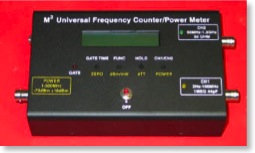
M3 Electronix FPM1 Power Meter / Frequency
Counter
I noticed this kit before the first of the year on the net, and was
really interested in it. I had previously built the M3
Semiconductor kit, and have been very happy with it. It has turned
out to be a valuable addition to my bench. I finally decided I
could not do with out this any more and needed to order one.
I ordered it on a Wednesday morning. Within an hour I received an
e-mail from Mike at M3 stating that my order was received and it
would ship out later that afternoon. I also ordered the matching RF
standard. Mike stated that they where still on his work bench for
burn in and testing, but would ship the following day.
The kit for the FPM-1 arrived in the mail on Friday. I spent Friday
evening reading the documentation and inventorying the parts. I
spent Saturday morning assembling the kit. Total build time was
about 4-5 Hours, I did not keep track of the time closely.
Construction:
I will include some notes and comments on the construction of the
meter. I deviated from the instructions in some places. I have also
added comments of things I would have done differently if I was to
do it again.
The inventory of the parts showed 1 extra 1K 5% resistor, and and 2
100K 1% resistors, but no 10K 1% resistor. I double checked them
with a meter to confirm that I was reading the colors correctly.
The Errata Sheet (Dated 8 Dec 2005) showed that step 13 was a 10K
1% [Brown-Black-Black-Red] resistor. [Brown-Black-Black-Red] is
also listed as the Color code for a 100K 1% resistor in step 5. The
schematic shows a 10K resistor for R12 so I am going to assume that
it should be a 10K resistor. I fired of an e-mail to M3 and they
confirmed that R12 should be a 10K 1% resistor. They also sent me
an updated Errata Sheet Dated 5 - Feb - 2006. That shows the proper
values and color codes for R12 and R21.
That leaves me with not having a 10K 1% resistor. I checked the
parts cabinet here, and no 10K 1% where to be found. I went through
a bunch of 10K 5% resistors to find one that was close. I can
change it back out later when I get the correct part.
There are some errors on the circuit board, and a few in the
manual. They are all well documented in the Updated Errata Sheet,
and all are very minor. All the circuit board errors are errors on
the silk screen, no traces have to be modified in any way.
Step
By Step Assembly:
I followed these steps in order, with the exception that I chose to
install all the 1% resistors first. I double checked all these with
a meter before installing.
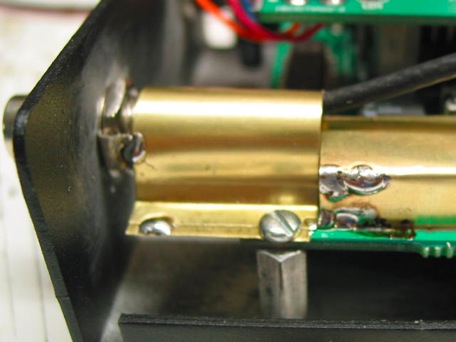
25) U4 7805 Regulator. See photo on page 4. Most of the body of the
regulator is off the board, not just the metal tab.
38) AJ4 Pay special attention to this. I bent the center pin to
make it fit on the board, but the screw hole on the keypad board
did not line up with the pot. Bend the leads on the pot so that the
body of the pot line up with the outline on the board closest to
C5. The photo below shows AJ4 incorrectly installed. If you install
it incorrectly like I did the leads will be too short to move the
the pot later, and you will have to file out the hole in the switch
board like I did.
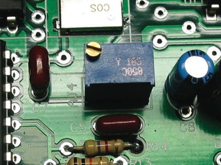
Note
Pot Not aligned with silkscreen
When
I was done I had the following parts left over:
1K 5% Resistor ( Was over in inventory)
52.3 1% Resistor
100 5% Resistor
1 10uF Electrolytic (Used Later)
1 .1 axial lead Electrolytic. (Used Later)
Stacking
and aligning the two circuit boards:
M) These wires will later be soldered to the power switch
K) Make sure that you can reach AJ4 through the hole in the switch
board. Because I mounted AJ4 incorrectly I had to file the hole
slightly.
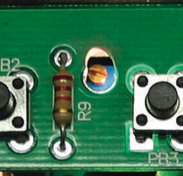
Hole
Filed to allow adjustment of AJ4
Putting
It All Together:
6. 4.5 Inches makes this tight, cut it to 5 inches
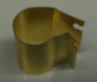
12. I made my final shield a little differently here. This design
makes soldering a little bit easier.
I would recommend that you skip the shielding in steps 12-13 for
now, and jump to the Let’s Make It Work Section. I had short caused
by the shield touching C26 and I could not get the Power Meter
calibration to work. I had to remove all the shielding to get to
the board.
Once you have steps 1-5 in the calibration section done you can go
back and install the shielding. You will have to do the calibration
steps again after all the shielding is in place.
Final
Shield In place
M3
Elextronix RF Calibrator:
I purchased the calibrator along with my kit. It can be used for
many more things around the shop after using it to calibrate the
kit. It comes fully assembled, Ready to use. It also makes
calibrating the kit very quick and easy.
Push Button Problems:
I had problems with clearance on my Gate Time button. When the case
was put on it would stick. I loosened all the screws and tried to
slide the boards to one side as far as they would go. I even took
the switch board off and tried to move the Gate Time button by
re-soldering it. I still had the binding problems. The tolerances
here are very close. I did not want to drill out the holes like the
manual suggested, and take a chance of messing up the nice paint on
the case. After looking at the problem a bit more, I decided that
the whole circuit board assembley needed to be move left about 1/32
of and inch.
Solution:
Remove the tapered screws holding the stand offs to the bottom of
the case. There is plenty of clearance in the holes for adjustment,
but the taper part of the screw do not allow for any adjustment. By
replacing these with standard flat screw you will be able to move
the complete circuit board assembly around to allow the buttons to
be centered in their holes.
Note: You might need to unsolder the shield from the power input
BNC connector to allow the board to move.
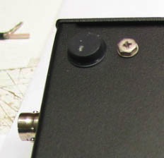
Flat
Head Screws
Conclusion:
The M3 Power/Frequency Counter is everything it is advertised to
be. There are a few errors in the silkscreen on the board, and some
changes on the schematic, but they are all documented in the errata
sheeet. The folks at M3 are top notch and the kit went together
rather smoothly. I will be using this kit for a long time to
come.
73’s de KB9JJA / Dale
M3 Electronix Web Site