Jetstream JTPS35BCM Switching Power Supply Mods
Review
Adding Anderson Power Poles
Modifying Fan Circuitry
I had purchased a 14 amp supply with meters from him previously, and have been very happy with it, with the exception of the loud fan.
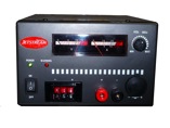
Jetstream
JTPS35BCM Switching Power Supply
When I saw that Jetstream had a new power supply with a battery
charger, and auto switch over circuitry I thought this would be a
good upgrade to my Astron 35M in a lighter package. I wanted
something that was lighter and more mobile for use in Field Day,
and other radio activities that required me to move my equipment
around. It has served me well in the shack, Running 24 hours at
Field Day, and powered my TS-2000 at Ellis Elementary School for an
International Space Station contact that our Radio Club set
up.
I did have a problem with the power supply when I got it. The Amp
meter did not return to zero, and was not reading accurately. A
called Jetstream to see if there was an internal adjustment I could
do, but was told no there was not. I could send the power supply in
and they would take care of it. It tool about 1 1/2 weeks to get
the power supply back, and all was well. The folks at Jetstream
where very friendly and helpful and I was happy with the turn
around. I also asked if a schematic for the power supply was
available, but was told they did not offer one.
This power supply has the same noisy fan that my 14 amp power
supply has. It does not come on as often, but when it does it is
loud, The good thing is that it does not run very long. I use this
power supply to run my Kenwood TS-2000 and my dual bander in the
shack, as well as assorted accessories. The power coming out of the
power supply is very clean when viewed on a scope, and I have not
found any noise on the HF bands even when using my little QRP
rigs.
The other thing that I did not like
about the power supply was that all the power connections are on
the front of the supply with the exception of the connection for
the battery which is on the back. This would be fine for a work
bench supply, but I like to keep my power supply for the radios
were I can keep an eye on the meters. With this type of
configuration you have the wires running from the front of the unit
which just does not look professional.
Pros:
Light Weight,
Adjustable Voltage
Lighted Meters
Clean Power
Battery Backup
Cigarette Lighter Socket on Front
Cons:
All the power connections are on the front of the unit.
Silly speaker wire power connection on front.
Loud Fan
As with anything there is
always room for improvement!
I use Anderson Power Poles on all my equipment, I like the
interchangeability of using them. Most of our Radio Club has
standardized on them as well, which makes it nice when we do
something like Field Day. I have some breakout boxes that have
Power Poles in them, but you always wind up with a rats nest of
wires. I wanted to add Power Poles directly to the back of the
power supply, and while I was at it I replaced the little speaker
terminals on the front of the unit with some also. These will be
handy for quick hookups of temporary equipment and such.
Standard Disclaimer!
There are very high voltages in side any power supply. Be sure to
unplug the supply while working on it. The capacitors in the supply
will also hold a charge even after it is unpluged. You should know
what you are doing before attempting any thing like this. I take no
responsibility for damage to your power supply, or harm to your
self, your equipment, etc. These modifications will definitely void
your warranty, and have the potential to cause you great harm if
you are not careful.
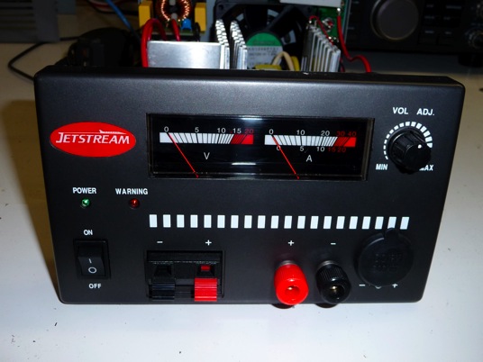
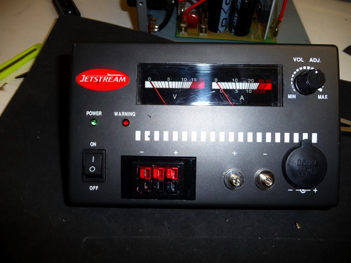
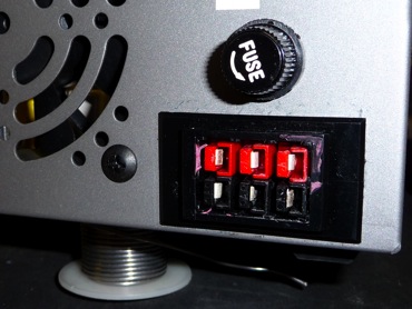
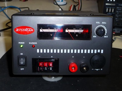
Front panel of stock power supply.

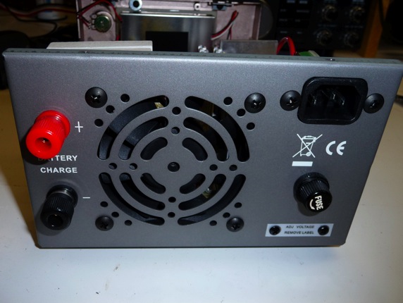
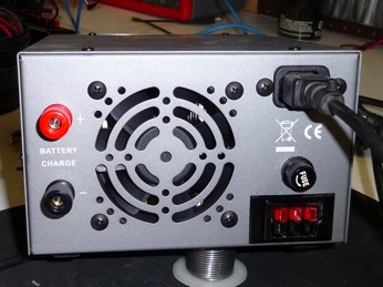
Rear of stock power supply. The Binding posts are for connection to
a 12 volt battery
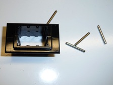
These are the Anderson Power Pole chassis mounts that I had on
hand.
These are actually designed for 2 sets of 3 plugs. They also sell
them in 2 pair and 4 pair configurations also.
The metal pins could not be used as I used these for 3 pairs of
two, instead of 2 sets of three.
To secure them I insearted my Power Poles with out wires, and glued
them into the chassis mount to secure them.
These can be ordered from
Connex-Electronics
Quick
Silver Radio
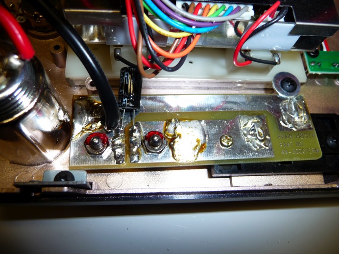
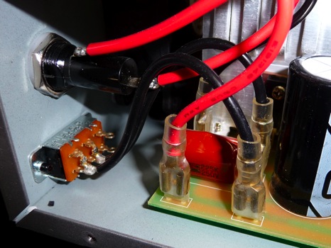
Once you have the front panel removed this is the circuit board
that the Binding Posts and Speaker Wire Type Connection is soldered
to.
You need to remove the board to make room for our Power Poles, and
we will have to cut part of the board off.
We will discard the Speaker Wire Type Connection and replace it
with out power poles.
The hole is a little smaller than the Chassis mount we are using
and you will have to make it larger to get it to fit.
I carefully opened the hole with an exacto knife and file.
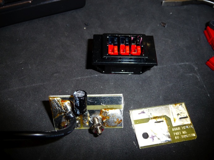
Here we see the board cut in half, as well as my Power Poles after
Glueing into the Chassis Mount
The 3 pair mount is a very good fit for this project, but I think
you could get the 4 pair Chassis mount to fit with a little more
cutting.
Note that the Binding posts have a threaded metal piece on the
front of the panel. I did not remove them from the board, but
instead unscrewed them from the front panel. You can see if the
photo that only the binding post on the right has the round
threaded nut attached.
Here is the back view after the chassis mount is in place. I
soldered the wires to what was left of the circuit board that the
binding posts are attached to.
This completes the modification to the front of the power
supply!
On to the Back!
There is not much room on the back of the power supply to add my
Power Poles.
On the right there is a switch to allow the operation of the power
supply from 110 or 220 volts AC.
As I will most likely never use the power supply on 220 volts, I
decided to remove the switch, and add my Power Poles there.
Here is the view of the 110/220 volt switch from inside the power
supply. The switch is on for 110 operation and off for 220.
The switch connects to the circuit board by the two black
wires.
Here the switch is removed, and a jumper soldered to the terminals
on the circuit board to permanently strap it for 110 volts.
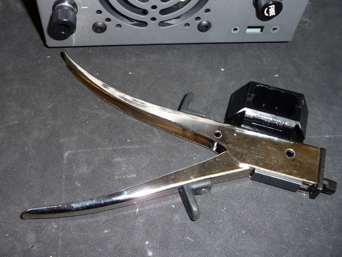
I used a sheet metal nibbler tool to open up the back of the
chassis.
Radio Shack used to sell these, I have also seen them in tool
catalogs, and on-line.
The nice thing about this tool is that it pulls the metal cutting
out so you do not get pieces of metal inside the case while you are
cutting.
I chose to leave the circuit board in the case while cutting the
hole. Be sure you can account for all the metal you cut away.
You do not want metal pieces floating around in the power supply
when you are done.
Do not use a Dremel or a file to cut the hole, the metal shavings
will get in the power supply and ruin in.
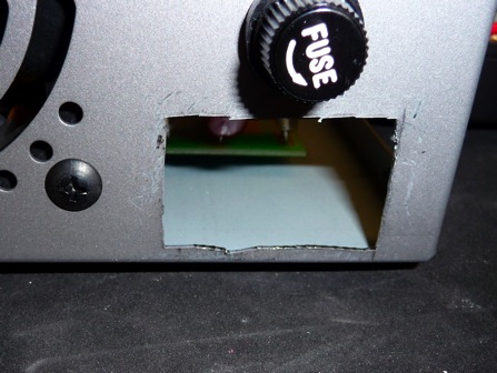
Here is the hole after I opened it up. The edges do not have to be
perfect.
The Chassis mount has a lip that will cover up the rough
edges.
Be sure to leave enough room at the bottom for the Chassis Mount to
fit.
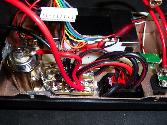
Power Poles in place on power supply.
As you can see the nibbling tool left some scratches on the back of
the case.
This could have been avoided by putting some masking tape on the
case to protect the finish while I was cutting the hole.
Next time I will remember to do this.
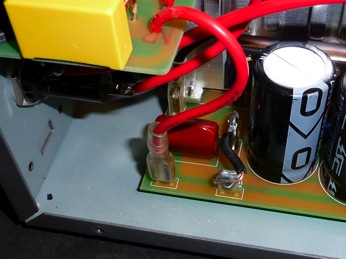
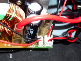
The power supply has an extra set of lugs on the circuit board were
the front panel gets its power from.
I simply connected the rear Power Poles to these with spade plugs,
and a length of heavy wire.
You can see that in the photo 2 down from here.
Now on to fixing that annoying fan.
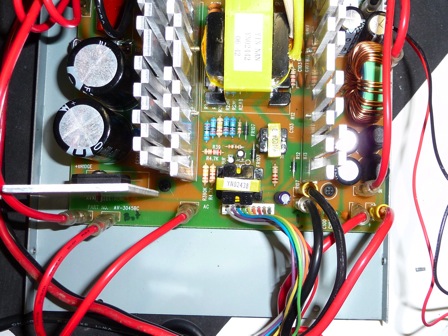
On the rear of the circuit board there are 3 connectors.
Left Connector goes to the lights on the meters
Upper Right is from the thermistor on the heat sink
Lower Right goes to the fan.
The circuitry to run the fan is very simple:
+12 volts goes to the fan at all times.
The ground lead to the fan is run through the thermistor, which
acts as an on off switch.
Once the thermistor gets warm enough it turns on and connects the
ground to the fan.
The fan comes on and pulls air over the heat sink until the
thermistor gets cool enough to turn off.
I had a few options here on how to modify this and quite the fan
down.
I could have replaced the fan with a quieter one.
Slowed the existing fan down so it was not too noisy.
Try to keep the power supply heat sink cooler so the fan does not
come on as often.
I chose the later. The reason being is that if the power supply
does indeed get hot enough I want the fan to run to cool it back
down.
So how do we keep the heat-sink cooler? By running the fan at a low
speed all the time.
To accomplish this we need to complete the circuit to the fan so
that it has a small voltage to constantly turn is slowly.
To do this we are going to add a 220 Ohm resistor from ground to
the ground side of the fan.
This value of resistor was chosen because it allowed the fan to run
at a slow speed, but is almost silent.
I added the resistor to the bottom of the circuit board, but then I
realized I could have just added it to the thermistor on the heat
sink. This would have been simpler and not required removing the
circuit board. Both ways accomplish the same thing.
If you choose to add it to the circuit board, there are only two
screws that hold the circuit board in place.
They are located towards the front of the board at the end of each
large heat-sink.
You do not have to remove the board, just slide if over a bit so
you can solder to the bottom of it.
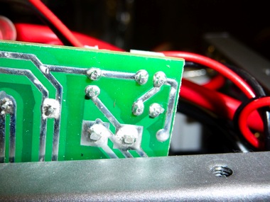
This is a view of the bottom of the circuit board.
We will be adding the 220 Ohm resistor from the square solder pads
to the upper most right pad.
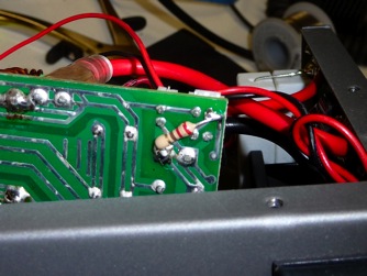
Here you can see the added resistor soldered in place.
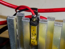
Here is the thermistor on the heat sink.
If you do it this way just solder the 220 Ohm resistor, with one
leg going to the black wire, and one leg going to the red
wire.
Be sure that the legs of the resistor can not touch the heat
sink!
Here is the completed power supply after it is put back
together.
And from the rear!
73’s de KB9JJA/Dale