This is a collection of information on the Icom PCR-1000 Receiver.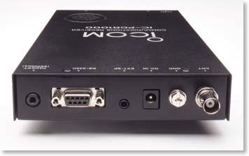
I purchased my PCR-1000 when they where first introduced at the Dayton Ham Fest. It has been one of the most versatile receivers in the shack. It serves as my reference receiver, as well as my make shift spectrum analyzer. Which it works very well for. It has become more of a tool than a general coverage receiver. I keep both the frequency and the S meter calibrated for use on the bench. This page will list a few projects that I have built to add to the capabilities of this fine receiver.
In my opinion the PCR-1000 is the best bang for the buck in a general coverage receiver today. Icom has recently introduced a replacement the CR-1500 and PCR-2500, but with the PCR-1000 going for about $300.00 used on ebay you can not beat it.
Deviation Meter:
I have built the meter, but have not documented it yet. It is only good to about 4.5 Khz but works very well.
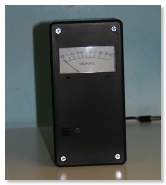
Deviation Meter - Plugs into the 9600 Baud Packet connector on the back of the radio
10.7 Mhz IF output:
The reason:
I wanted to play with a few things like Digital Radio Mondale (DRM) and Software Defined Radio (SDR).
DRM uses a 12 KHz IF. I have modified my Kenwood TS-2000 to bring out the 12 Khz IF out the ACC2 connector. I will be building a converter to take the 10.7 Mhz IF out and convert it down to 12 Khz for the PCR-1000 in the future.
I also wanted to add a SDR back-end to my PCR-1000 This would allow me to use the front end of the PCR-1000 to tune anywhere in the band and use a Soft Rock 40 Lite as the SDR back-end for decoding.
One of the other considerations is that I am in the planing stages of building a Scotty's Modular Spectrum Analyzer, which also has a 10.7 Mhz IF. So anything I build as an add on to the PCR-1000 will also work with my MSA when it is completed.
The Research:
After a little research I determined that I wanted to take the 10.7 Mhz IF off before as many IF filters as I could. After probing around with the oscilloscope the output of Q85 seemed like the best place to get what I was looking for. I also tested a few different values of capacitors to see which would preserve the signal the most. I like the .1uf the best.
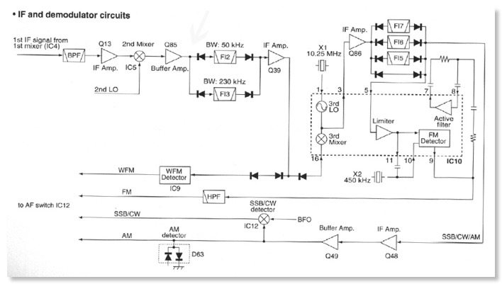
Block Diagram of the front end of the PCR-1000
Note that Q85 only has the Band Pass Filters in front of it.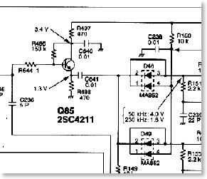
Schematic showing Q85
The Dirty Work:
The signal is taken off with a .1uF capacitor to get rid of the DC voltage, and fed to the back of radio to a SMA jack that I added just above the external speaker connector. To get the cable out of the RF shielded part of the radio I used my sheet metal nibbler to notch a section out of the back vertical shield.
Notch In rear vertical panel for coax
The PCR-1000 is all surface mount and the traces are very small and fragile. Using a small piece of coax cable would put more stress on the traces of the circuit board that I would be comfortable with. I came up with a system that would put little if no stress on the small traces. I cut a small piece of coper clad circuit board and glued it to the ground plane near Q85. This would allow me to install the small .1uf capacitor to the PCR circuit board and my small pad that I had glued down. The larger surface of the new pad also makes installing the small piece of coax cable much nicer. I also installed a small solder lug under the nearby ground screw to secure the shield of the coax to. This makes for a very rigid installation, and there is no worry about damaging the PCR board.
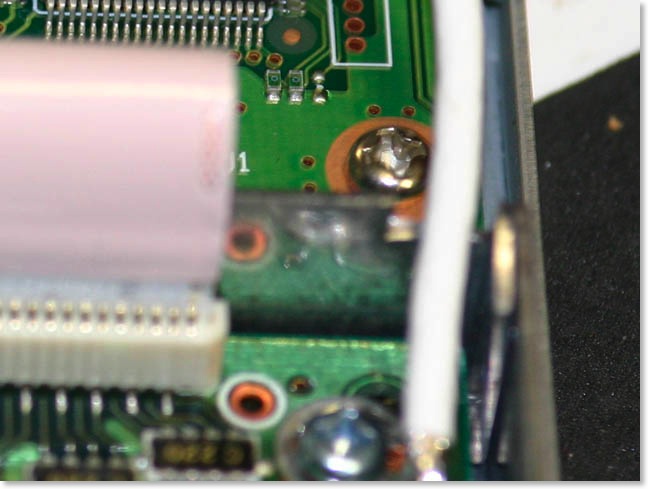
Here is the capacitor mounted to the PCR-1000 and my small Coper Clad Board
Super Glued to the ground plane. Notice the small metal tab added under the screw.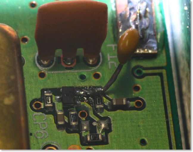
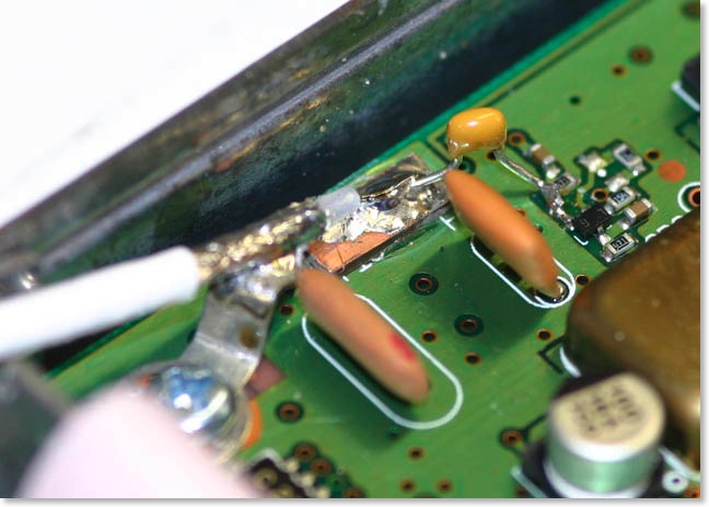
Here is a close up of the solder connection to Q85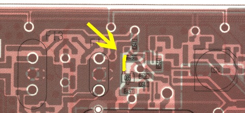
The yellow area is where you want to solder the cap into
I drilled a hole in the back of the radio for a chassis mount SMA connector I had on hand. I did not remove the circuit board while drilling, which is a dangerous thing. I blocked the area up with masking tape before drilling to keep the metal chips from getting into the radio. I also used a shop vac to vacuum up the chips as I drilled. Mr Murphy came to visit while I was drilling, and the large capacitor directly behind where I was drilling met the drill bit and tore a trace off the board when it came loose. The capacitor was not damaged, but I had to repair the trace on the board as well as glue and solder the capacitor back it place. The spacing for the SMA connector is very tight, there is just enough room to plug the speaker back into the radio. There is less than 1/32 of an inch clearance between the two.
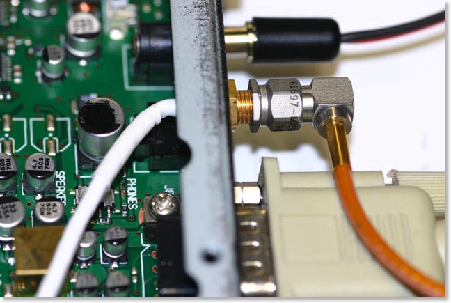
SMA jack mounted on the back of the PCR-1000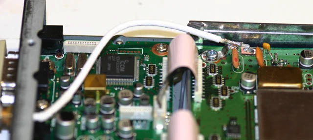
Coax path to the back of the radio
The SDR:
The IF output works great. I built a Softrock Lite with a crystal that puts it about 38500 Hz above 10.7 Mhz so I have to tune the PCR-100 up about 38500 Hz above the frequency I want to look at to see the signals in the band pass (I am using Rocky software with mine).
The Softrock Lite version 6 for a 10.7 Mhz IF comes with a crystal that is 14.318 Mhz The Softrock is configured to 3*F/4 so the actual frequency of the softrock kit as shipped by Tony comes out to 10.738.500 Mhz This is the reason for the 38500 Hz difference
A crystal with a frequency of 14.26667 Mhz will put the softrock kit directly on 10.7 Mhz.
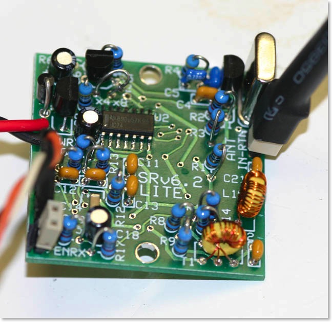
Softrock Lite for 10.7 Mhz IF before mounting in external case
Using Separate antennas for HF and VHF
I was planing on building a diplexer to allow the use of separate receiving antennas and eliminating the switch I have to select between my HF receiving antenna and my discone for vhf.
I have reviewed the schematic and have determined it is possible to put separate antenna connectors on the PCR-1000 for each. There are a few downsides to doing this. 1. The built in attenuator will only be available on one of the antenna connections. 2. There is not room on the PCR-1000 for the 2nd antenna connector.
Another option is to build a box that lives outside the PCR-1000 that has two antenna connectors and run a control line from the pcr-1000 to this box that would select the correct antenna based on the tuning range of the pcr-1000. The control signals are available to make more then 2 antenna connections available for example, I could have HF, 6 Meter and VHF. The disadvantage of this is that the relays would get a work out if you where scanning multiple bands.
I am most likely going to build the diplexer for now, and will update this page with more details.
Links to other PCR-1000 Resources on the net:
PCR1000 EEPROM corruption FAQ.
TalkPCR Version 2.4
PCR-1000 Mailing List Archive: By Thread at wenzel.net
Yahoo Groups PCR1000 Yes there are multiple groups
Yahoo Groups PCR-1000
Yahoo Groups PCR_1000
Yahoo Groups for the new PCR 1500 and IC-R1500
Yahoo Groups for the new PCR-2500 and IC-R2500
Icom PCR Hardware Controller
PCR-1000 - The RadioReference Wiki