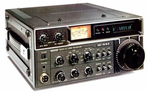
Icom 551
The Rig:
I purchased my IC-551 used, and in working but unknown condition from a fellow ham. It was known that it had a few problems, and was priced accordingly. I wanted it primarily to monitor the 6 Meter SSB calling frequency. None of the options are installed in the unit. There is also a relay held in with duct tape, and wired to the auxiliary jack on the back of the rig. The internal power supply was not functioning, the squelch did not work, and it was off frequency. The Audio Gain knob was also missing.
Basic clean up:
All the controls where dirty, with the squelch being the worst, it is also the hardest pot to get to. I cleaned all with Radio Shack contract cleaner. The squelch did not improve much so I cleaned it again, and it seems to be a little better, but still not perfect. I will revisit it in the near future if it does not clear up with use. I removed the power supply from the unit for now. I also removed the relay and associated wiring, I could not have something held in with duct tape in one of my rigs.
Alignment:
I found a copy of the service manual, and proceeded to align the frequency and the VCO of the unit. The trim pots that Icom used in this rig are like no others I have seen. They basically have a small hole in the center and a notch on the side of the wiper. I made a tool out of an old plastic coil alignment stick. I cut off all but a small part of the flat screwdriver tip, so that it would fit in the little slot on the edge of the pot, then heated up a straight pin and pushed it into the center of the tool, and clipped off all but about 1/16th of an inch. The pin keeps it centered, and makes turning the little pots very easy.
S Meter:
I also adjusted the S meter so that S9 and 60 over would be calibrated values. The meter does not track too bad, and I am happy with the results, and will not pursue the S meter any further.
The power supply:
The supply that was installed in this unit was putting out about 24 volts open load, it would drop to about 8 volts with a small load installed on it. The service manual shows a switching type power supply, but this was a good old linear type. The service manual mentioned nothing about this type of power supply. I checked the service manuals for the 2 meter, and 440 versions of the radio which also showed a switching type supply. I had noticed that there was a burnt resistor near the large electrolytic capacitor. It was burnt beyond recognition. I removed the resistor and it measured about 340 ohms. In most cases a resistor goes up in value when it burns. An old trick that I learned when I worked in the TV shops in my high school days was to cut a bad or burnt resistor in half and measure each side. In most cases you can determine the original value as one half will give you the expected value and the other halve will be way off, in most cases high or open. This resistor measured about 160 ohms in each half. I decided to error on the side of caution so I replaced it with a 1K ohm only because most of the other resistors on the power supply board where 1K. The supply was still not working, and the resistor was warm, but it did not get hot and burn. I decided to check the large transistor that was part of the power supply but attached to the chassis of the radio. This transistor tested bad with my meter. The part number on it was XXXXXXXX. I did not have a replacement in stock and a NTE replacement was $23.00. I checked the specs and determined that a 2n3055 even though in a different package would exceed the specifications of the factory transistor. With it wired in with alligator clips and jumpers, and upon testing I was now seeing about 3 volts on the output. I then changed the 1K to a 330 ohm resistor and the output came up to 13.4 volts. Not wanting to drill the chassis out to accept the TO-3 cased 2N3055 I will order a TIP3055 which has about the same specs but in a TO-220 package, and less than $3.00 from Mouser.
Conclusion:
I am happy with this radio for its intended purpose. I am told that the audio sounds good, and have been using it for local QRP QSO's. When the parts get here I will re-install the power supply, but will most likely continue to run it off of 12 volts. The only thing left to do is find an audio gain knob for the rig. As I do not have the proper power plug for the rig, I will most likely replace the Icom plug with Anderson Power Poles.
Some notes I found on the web for this rig are duplicated or linked to below.
Icom 551 Operators and Service Manual
--------------
Icom IC-551D (IC 551 D IC551D) Frequency Alignment
| Locate R122 near center of main board, directly in front of center mounting screw. The top of this resistor is bare and is used as the test point for the BFO. Connect frequency counter to this point. |
| Set mode switch to LSB. (Dial frequency unimportant) |
| Adjust C105 for 9.013000 MHz. |
| Set mode switch to CW. |
| Turn on RF power control and set at minimum power output. |
| Set receive/transmit switch to transmit. |
| Short CW key jack on rear of radio or close CW key if attached. |
| Adjust L33 for 9.010500 MHz. |
| Return to receive. |
| Set mode switch to USB. |
| Adjust L32 for 9.010000 MHz. |
| Set mode switch to CW. |
| Adjust L31 for 9.009700 MHz. |
| Remove cover from PLL unit. |
| Locate R44 near rear of PLL unit. The top of this resistor is bare and is used as the test point for the VCO. Connect frequency counter to this point. |
| Set mode switch to LSB. |
| Tune dial to 50.101.5 MHz. |
| Adjust R59 for 41.088500 MHz. |
| Tune dial to 50.101.4 MHz. |
| Adjust R60 for 41.008400 Mhz. |
| Dial 50.100.0 MHz. |
| Adjust L8 in FM unit for 50.100000 MHz on transmit at output to dummy load. |
Icom IC-551D (IC 551 D IC551D) EX-108 P.B. TUNE UNIT -- Installation
The EX-108 mounts to the upper mounting plate as shown on page 29 of the manual.
1. Attach the EX-108 to the upper mounting plate with 4 screws.
2. Route cable behind front panel to top of main circuit board.
3. Remove jumper cable connected between J2 and J3. Connect EX-108 cable to J3.
4. If your radio has a choke coil (L44) next to J3, remove it.
5. The cutoff bandwidth is about 700 Hz at -6db point. For CW, unit gives +/-500 Hz BW at -6db point and is adjustable. This unit also contains a speech processor for SSB use
Icom IC-551D (IC 551 D IC551D) to rx down to 47.000 MHz
First, dial down to the bottom end of the band, eg 50.001, on usb. Press the button on the left side of the dial so that the red light comes on. Keep on pressing this button with your right hand/finger. Now with your left hand change the mode from usb to fm and back, do this many times and you will see the freq going down in 10 increments.
You will notice that the freq read out will not show 49mhz but 59mhz, ignore this. I have listerned to cordless phones down at "59mhz". Take the freq read out down to 48.999mhz, "58.999mhz," only then can you use the dial to dial down after letting the button go. Anything between 48.999mhz"58.999mhz" to 49.999mhz "59.999mhz" will revert back to 53mhz if you let the button go and try to dial down. Between 48.999 to 49.999 you can ownly dial up.
I have listerned to video signals from Europe on 48.250mhz "58.250mz" I hope you have luck with this.
Icom IC-551D (IC 551 D IC551D) Modification af the ScanRate and ScanSpeed
Introduction:
Here is a modification for the IC-551D 6-metre multimode radio. The mod. may be applicable to other ICOM radios of that era, eg, the 2-metre version (IC-251?, IC-211?). It is easily carried out and consists of soldering a jumper wire between two other wires. No major disassembly is required.
Background:
When the 'VFO' switch is set to the 'MS' position, the IC-551D can be made to scan three user-programmable frequencies. Unfor- tunately, after scanning has stopped on an active frequency, it never re-starts, even if the signal disappears from the frequency. The radio remains on that frequency indefinitely. The user is forced to manually re-start the scanning, and the cycle repeats when an active frequency again opens the squelch.
Modification:
This mod. will cause the scanning to pause on an active frequency for approx 10 seconds; scanning automatically resumes at the end of the 10 seconds whether the signal is present or not. In essence the mod. consists of changing the 'MS' scan regime from the band-scan 'MODE A' regime (permanent stop) to the band-scan 'MODE B' regime (pause).
Note:
The IC-551D handbook says that the pause in 'MODE B' is sixteen seconds, whereas in my radio it is close to ten seconds. It's possible that ICOM revised the design after the handbook was printed, or perhaps the 10-second characteristic of my particular radio is a result of long-term component drift. Whatever, the point here is that the same pause will be used for the 'MS' scan mode as is already used in the 'B' scan mode. So in your particular radio the pause may be 10-16 seconds.
Scan Rate:
After modification the scan rate becomes adjustable by the 'SCAN SPEED' control, which was previously rendered non-operative in 'MS' scan mode, although it was operative in the two band-scan modes, A and B.
Procedure:
Remove the power plug from the rear of the IC-551D. Turn the set upside-down with the rear closest to you. From this point on, all expressions such as 'left', 'right', 'up', 'down', refer to the radio as viewed by you in this orientation.
1. Remove the four bottom cover screws and CAREFULLY remove the bottom cover, disconnecting the speaker plug as you lift it away.
2. If your IC-551D does not have the optional FM board installed, go to Step 3. Remove the FM board by disconnecting the white plug from the left corner and removing four screws (two at each end). Lift the FM board away carefully as it's still attached to the radio by a flying cable, and place it on the front corner of the case.
3. Remove the sub-bracket on which the FM board was mounted by removing the screws at each side (in my radio: 2 on LHS, 1 on RHS).
4. Cut a length of light, flexible wire 50-60mm long and strip 3mm of insulation from each end. Tin both ends of this jumper wire with solder.
5. Observe the printed circuit board mounted vertically about 40mm behind the front-panel controls. This PCB is the 'DRIVER' board. This is a CPU/digital processing board and has nothing to do with the transmit driver stages. Observe the three white plugs/sockets (headers) along the upper edge of this PCB. On the left-most header (closest to the centre of the radio) count the wires from right to left as they exit from the plug. This is a six-wire plug/socket (J2/P11). The second wire from the right is a dark-green wire. This is the 'VFO B' wire. DO NOT cut this wire. At some convenient point, strip about 4mm of insulation from it with a razor blade. Tin the exposed wire and solder one end of your 50-60mm jumper wire to it. Caution: In some photos in the ICOM documentation J2/P11 are shown fitted to the front-panel side of the PCB, rather than the rear side. If J2/P11 have been fitted this way in your radio, you must still use the second wire from the right, since the PCB layout does not change. However, the wire may not be dark-green as the colour sequence may be reversed.
6. Look down the left-hand edge of the same PCB. Observe the white plug/socket header, the first one you come to as you look down the edge of the PCB. The header is J4/P7. Count the wires as they exit plug P7. The third wire (counting downwards) is an orange wire. This is the 'MS' wire. To make this wire accessible, prise P7 off J4 with a screwdriver and pull P7 up towards you. At some convenient point, cut the wire, creating two ends, one going into P7, the other coming from the loom. Ignore the wire going into P7, it will not be used. Instead, take the wire which comes from the loom, strip 3mm or so of insulation from it and tin it with solder. Solder the free end of your 50-60mm jumper wire to this tinned end.
7. Push P7 back down into the wiring and press it back onto J4. This is a little tricky, but is best done with a short, skinny, screw- driver.
8. Re-fit the FM board sub-bracket and re-fit its screws. Re-fit the FM board to the bracket and re-fit its screws. Plug in its header plug. Ensure that both of your soldered connections and the cut-off end of the 'MS' wire are clear of metal framework, shield compartments. The rest of the re-assembly is in reverse order to that described earlier.
Testing:
Turn on the IC-551D. Program three frequencies into memory positions 1,2,3. Set the 'VFO' switch to 'MS' and initiate scanning by pressing the 'MS/MW' button. When one of those frequencies becomes active, scanning will pause for 10-16 seconds; scanning resumes auto- matically at the end of the pause, whether the signal is present or not. When receiving a prolonged transmission, reception is briefly interrupted every 10-16 seconds as the scanning re-starts. When two or three of the frequencies are active, each transmission is heard in rotation for 10-16 seconds, eg. 1,2,3,1,2,3.
Scanning can still be stopped and re-started by pressing the 'MS/MW' button. The rate at which the frequencies are scanned is now adjustable by the 'SCAN SPEED' control, accessible by removing the small cover in the top of the case. It's probably best to set the control at the slowest setting (fully anti-clockwise). If set too fast, scanning may not stop on active frequencies. No other function of the IC-551D is disturbed by this modification.
I use my IC-551D in the 'MS' scan mode to monitor my three favourite 2-metre repeaters, using a home-brew 144-50 MHz converter connected to the IC-551D.